Skip to content
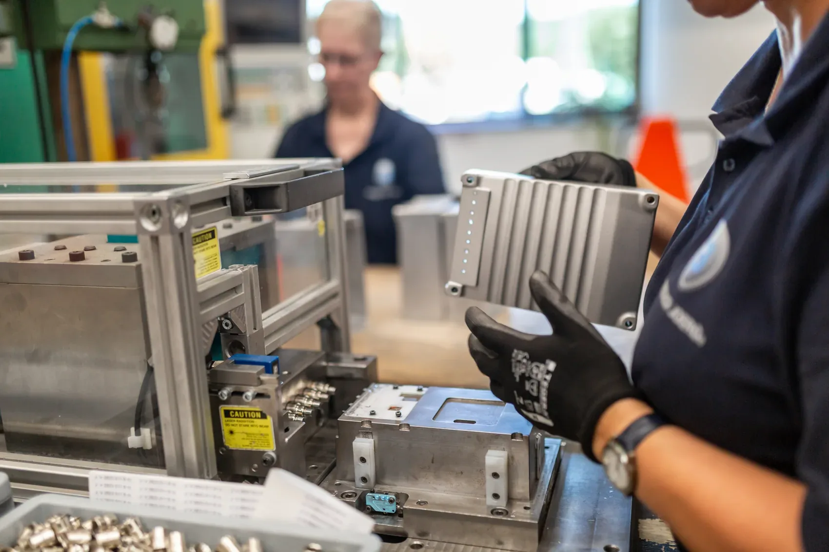
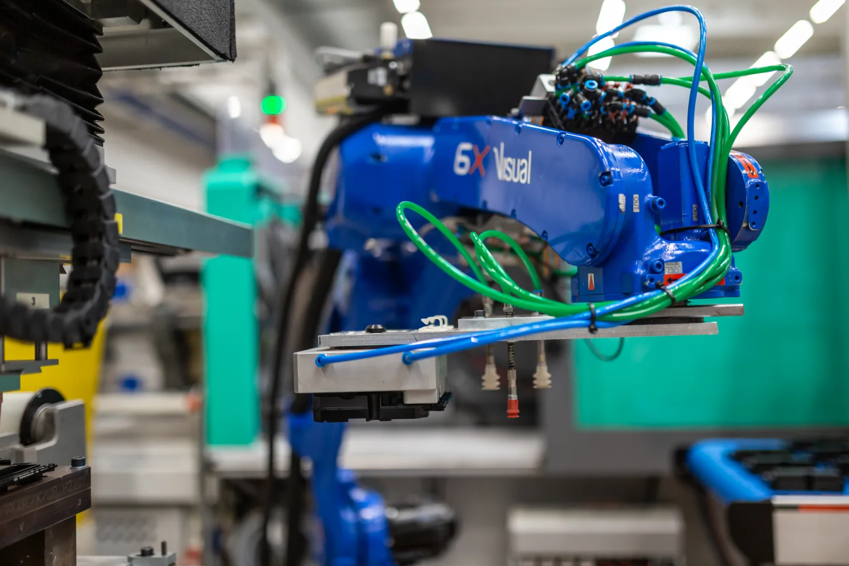
Sepro 6X Visual handling robot with gripper at an injection moulding cell at Friedrich Joerg

Capabilities

From the metal-plastic bond to the ready-to-install assembly: eight capabilities, combined at one site, since 1920.

Core Material composites · 01 Moulding · 02 Stamping · 03 Toolmaking · 04 Engineering · 05 Assembly
Friedrich Joerg GmbH
DesignationCapabilities
Scope8 areas
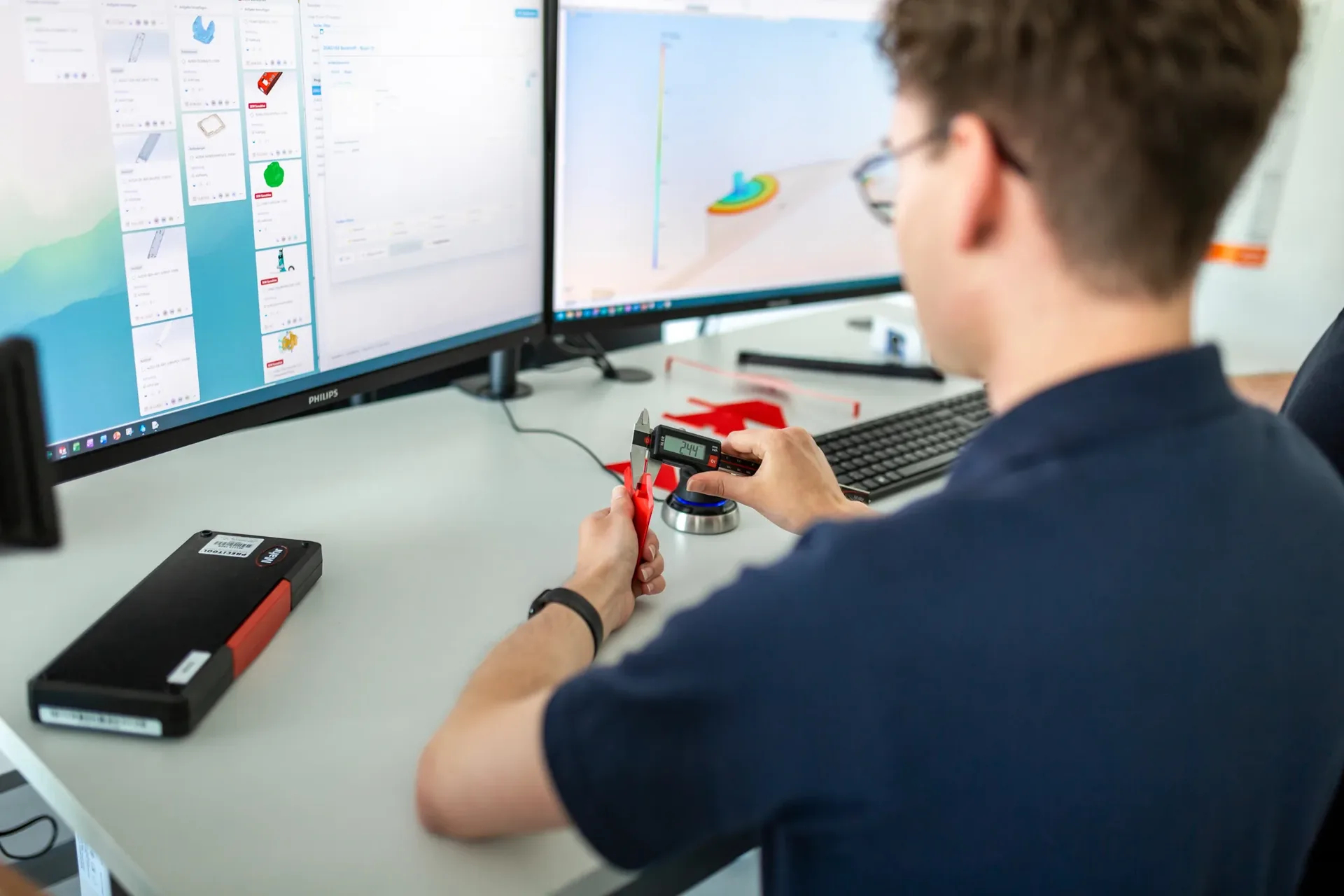
Friedrich Joerg design engineer checking a part with a calliper and evaluating the results digitally
01Capability

Engineering for series production

Series readiness begins before the first tool is built. In simultaneous engineering, we align part geometry, material, tolerance chains, manufacturability, tool concept and total cost at an early stage. Toolmaking, production and quality work together from the outset, so that technical and commercial risks are identified before they become expensive in the tool or in series production.

What we validate before tool release

  • DFM review (design for manufacturing) of the part geometry for injection moulding, stamping and bending, and assembly
  • Material selection by function, load, temperature, media and certification requirements
  • Tolerance chains and interfaces between metal, plastic and assembly components
  • Filling, cooling and warpage analyses for injection moulded parts, with Moldflow where required
  • Tool, process and automation concept geared to economical series production
  • Quality-critical characteristics, testability, and production and relevant life-cycle costs

Result

A documented DFM report with clear recommendations, technical risks and a sound basis for tool and process release. This reduces late changes and makes costs, deadlines and series start-up easier to plan.

3D part in engineering

360° from design data

A2473 · DFM review

Before tool release

For the holder arm A2473, we added a functional plastic bayonet lock to the original part data. Locking geometry and local stiffness were matched so that the required snap-in and release forces were achieved: loaded areas were stiffened, others deliberately designed to be flexible. The documented optimisations went directly into the 3D data before toolmaking.

Article
A2473 · Holder arm
Phase
DFM and process design
Focus
Manufacturability and series risks

02 · Material composites & functional integration

When metal and plastic become one part

Our strength lies in how the processes work together. We combine different materials into a functional unit and integrate additional functions directly into the part, from light guides to media seals.

Metal and plastic react differently to temperature changes, vibration and mechanical load. A material composite that works reliably over time is therefore not created by overmoulding alone. What matters is the interplay of material pairing, part geometry, surface, tool design and stable process control.

Depending on the application, undercuts and other geometric anchoring features secure the form fit. Where the material pairing requires it, suitable surface treatments or adhesion promoters are also used. Tool temperature control and matched process parameters help to limit internal stresses and to produce the bond reproducibly in series.

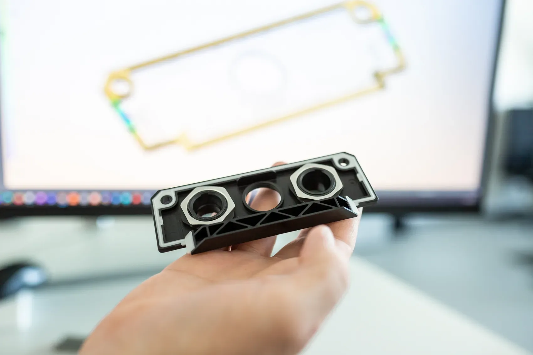
Series part and its CAD model, where the metal-plastic interface is designed

The material composite begins in the design: material pairing, anchoring geometry, sealing areas and process control are defined before the first tool is built.

01

Insert moulding

Anchoring metal inserts in the plastic by form fit

In insert moulding, a prefabricated metal part is positioned in the mould and then overmoulded with plastic. Undercuts, knurling or other anchoring geometries secure the bond against twisting and pull-out.

This is how nickel-plated brass threaded bushes are anchored by form fit in the glass-fibre-reinforced PBT of a terminal block for frequency inverters from 24 to 1,000 V. The bond can transmit the required torque, while a later joining and assembly step is no longer needed.

02

Outsert technology

Plastic functions on a metal carrier

In outsert technology, plastic or elastomer functions are moulded onto a comparatively large metal carrier in a targeted way.

On a base plate for electric motors, a sealing geometry made of thermoplastic elastomer is moulded directly onto the die-cast aluminium carrier. The seal is therefore clearly positioned during manufacture. Separate inserting and fixing is no longer needed.

03

2K hard-soft

Carrier and seal in one process cycle

In 2K injection moulding, the hard and soft components are processed one after the other in one mould. First the load-bearing hard component is formed, then the sealing geometry made of a thermoplastic elastomer is moulded directly onto it.

On an electrical cover, a polycarbonate carrier and the directly moulded-on TPE seal form a single part. This eliminates the separate insertion of a seal, and its position is reproducibly defined. The required sealing performance is designed and tested in the fully assembled unit.

3D part in detail

360° from design data

A2305 · Insert moulding

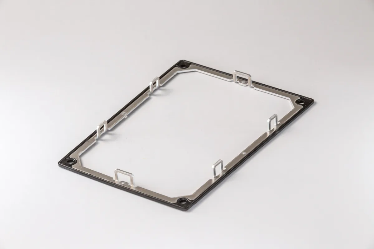
Aluminium frame and TPE seal in one part

In insert moulding, the aluminium frame is positioned precisely in the mould. The thermoplastic elastomer is then moulded directly onto the frame. TPE can be processed like a thermoplastic and behaves elastically in later use.

The two materials perform different tasks: the aluminium frame dissipates heat from the electronics area, ensures dimensional stability and supports the sealing geometry from the inside. The moulded-on TPE takes on the elastic sealing function. The result is a part with integrated functions that requires no separately fitted seal.

Article
A2305 · Aluminium frame with integrated TPE seal
Process
Insert moulding with TPE
Materials
Aluminium and thermoplastic elastomer
Functions
Heat dissipation, dimensional stability and sealing

One part. Three functions.

Dissipate heat. Support the seal. Save assembly.

Within the assembly, the aluminium frame performs a thermal and a mechanical function at the same time. It dissipates heat from the electronics area and stabilises the geometry of the part. At the same time, it supports the moulded-on TPE seal from the inside, so that its position and contour remain permanently defined.

7–8 K

lower part temperature thanks to the aluminium frame

CAPTIVE

TPE seal permanently positioned on the frame

ONE OPERATION FEWER

no separate seal assembly required

The elastic TPE forms the actual sealing geometry. Because it is moulded directly onto the frame, the seal is captively connected to the part and protected against shifting during handling, assembly and external stress. The bond is designed for the intended life cycle of the product.

At the same time, the separate provision, positioning and assembly of an additional seal is eliminated. Two materials thus become a ready-to-assemble part that combines heat dissipation, dimensional stability and sealing.

Toolmaking hall with machining centres at Friedrich Joerg
03Capability

Toolmaking & automation

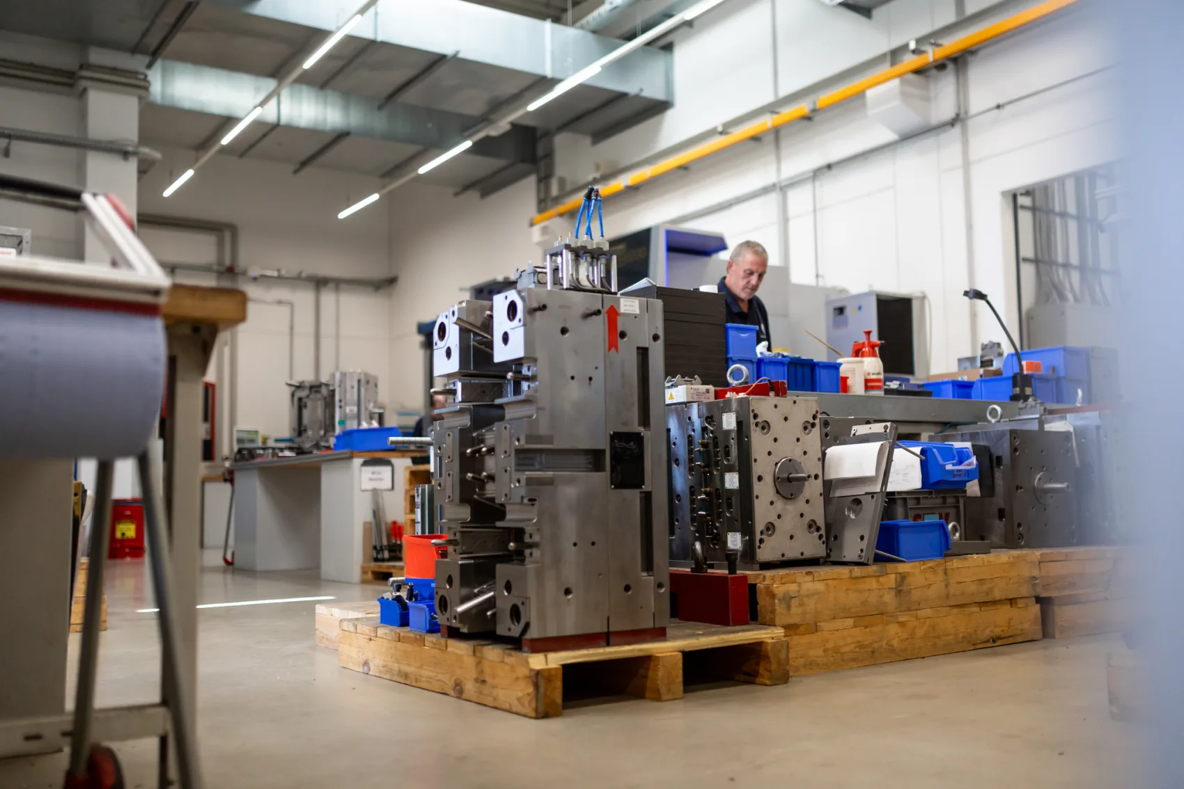
Series quality begins with the tool and comes from the stable interplay of tool, machine, handling and inspection. We develop, design and build injection moulds and stamping and bending dies, as well as assembly, inspection and automation solutions, in-house.

Toolmaking is where it is decided whether a solution runs stably in series. We design injection moulds and stamping and bending dies in 3D CAD and manufacture the required components by CNC wire EDM, die-sinking EDM, milling, turning and grinding. Design, manufacture, tool assembly and maintenance are aligned with each other from the start. When tools need to be adapted, serviced or repaired, the routes stay short in-house. This reduces response times and production interruptions.

Series production takes more than the tool. We source base machines, drives, linear axes and robots from established manufacturers. We develop and implement the application-specific system concept, assembly stations, grippers, fixtures and the mechanical and electrical integration ourselves. In a linear concept, one unit moves to several assembly stations. Alternatively, the system can be built as a rotary indexing system. Control systems and programming are also created in-house.

What we can do

01

In-house tool design

Design in 3D CAD, closely coordinated with development and production. Laid out from the start for the series process, assembly and maintenance.

02

EDM & machining

CNC wire EDM and die-sinking EDM with Fanuc and Mitsubishi controls. Milling, turning and grinding for complex contours and precise mould inserts.

03

Application-specific automation

Bought-in base machines, drives and robots. Our own assembly stations, gripper systems, module heads, fixtures, system integration and programming.

04

Changes & maintenance in-house

Adaptation, servicing, repair and trials in our own toolmaking shop. Short response times without external transport and coordination.

Tools and production

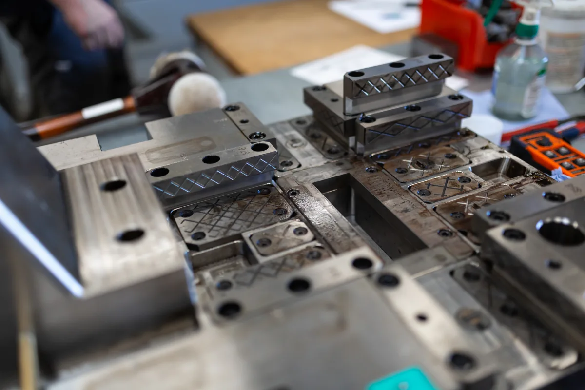
Nozzle-side mould half with removed slides during cleaning and maintenance
Tool maintenanceNozzle-side mould half with slides removed for thorough cleaning and maintenance.
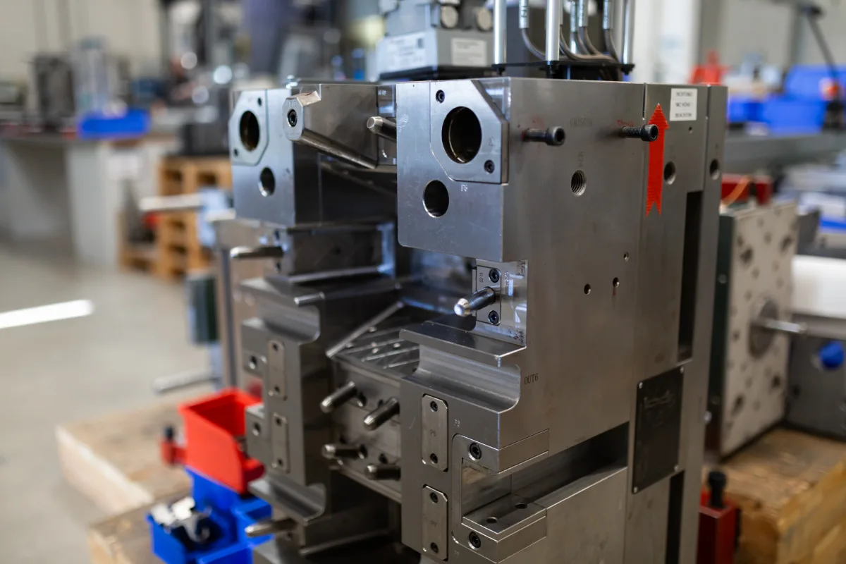
Ejector side of a hot runner mould with slides and angle pins
Hot runner mould with slidesEjector side with angle pins for the slide movement during opening and closing.
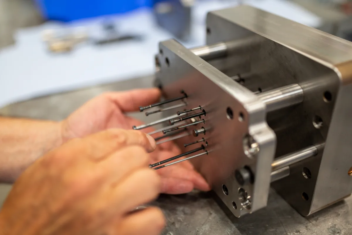
Fine ejector pins being inserted by hand into the ejector plate
Ejector plate with fine ejectorsFine ejector pins are fitted precisely into the ejector plate.

3D tool in detail

360° from design data

A2272 · Injection mould SVB14

From 3D CAD to series tool

Shown is an open injection mould with a view of the nozzle side and the ejector side. Mould inserts, gating, guidance and temperature control are matched to the part geometry and series process as early as the 3D CAD design. Design, manufacture, assembly and trials take place in our own toolmaking shop.

Article
A2272
Tool
SVB14
View
Nozzle and ejector side
Basis
3D CAD design
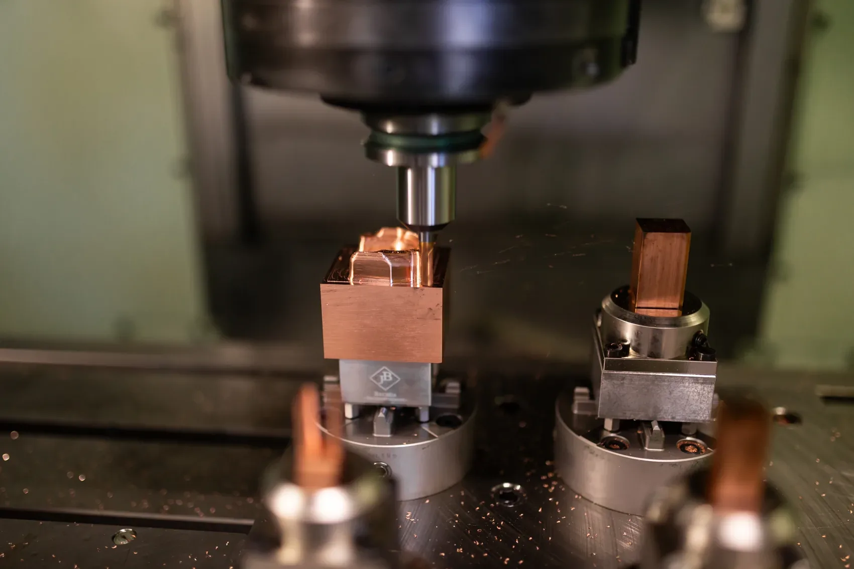
CNC machining of a copper electrode in the Friedrich Joerg toolmaking shop

From the toolmaking shop

We mill the copper electrodes for our injection moulds ourselves and use them for die-sinking EDM of the mould inserts. Copper is particularly suitable for fine contours and high surface quality. This produces precise cavities for reproducible series parts.

Frequently asked

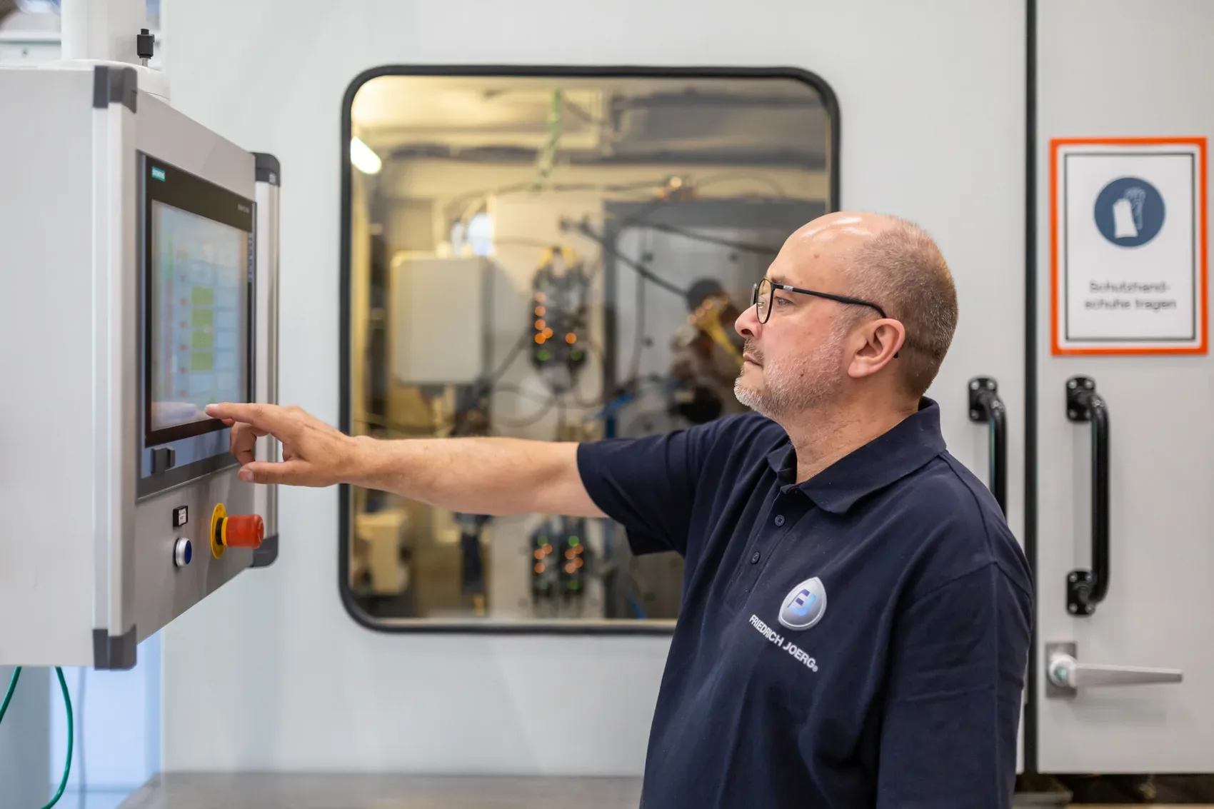
Operator at a fully electric Arburg injection moulding machine at Friedrich Joerg
04Capability

Plastic injection moulding

On 21 injection moulding machines, including fully electric machines, we produce single and multi-component parts from engineering and high-performance thermoplastics. With 1K, 2K, insert and outsert processes, we integrate metal parts, seals and other functions directly in the mould. Where required, we then also take on assembly into the complete electromechanical assembly.

For our customers, both the precise individual part and the fully functioning assembly can be decisive. That is why we do not look at even a simple injection moulded part only by its drawing: we take function, mechanical loads, installation space, interfaces, tolerances and ambient conditions into account, and consider the later assembly from the start.

Where the task makes it sensible, we integrate further functions directly into the injection moulding process: for example contacts and threaded bushes, including from our own stamping and bending technology, hard-soft bonds or seals. This lets us deliver exactly the degree of integration the project needs, from the demanding individual part to the ready-to-install assembly.

We select materials together with our customers based on the actual requirement profile. Decisive factors include mechanical loads, impact strength, dimensional stability, temperature, vibration, humidity, UV radiation, chemicals and cleaning agents, as well as fire behaviour and certification requirements.

We process standard thermoplastics, engineering thermoplastics, high-performance thermoplastics and thermoplastic elastomers. We keep many common material grades in stock; special compounds are selected and sourced for the application.
21

Injection moulding machines from Arburg and Demag

1K · 2K

Single and multi-component injection moulding

PE TO PEEK

Thermoplastics and TPE

What we can do

01

Insert moulding

Metal parts are positioned precisely in the mould and overmoulded in a targeted way. This allows, for example, nickel-plated brass threaded bushes to be integrated permanently and in exact position into the glass-fibre-reinforced PBT of a terminal block, without a downstream assembly step.

02

Outsert technology

In the outsert process, functional elements made of plastic or TPE are moulded onto a metal carrier in a targeted way. On a base plate for electric motors, the TPE applied directly to the die-cast aluminium seals between the motor and the terminal box.

03

2K hard-soft in one process

A dimensionally stable carrier part and an elastic sealing component are produced one after the other in one mould and one automated process. This saves separate seal assembly and reduces the risk of missing, shifted, crushed or folded seals.

04

Materials with a function

Our processing range extends from PE and ABS through POM, PBT, PC, PA 6 and PA 66 to the high-performance thermoplastic PEEK and thermoplastic elastomers. Depending on the requirements, we use unreinforced, glass-fibre or glass-bead filled, as well as UV-stabilised and flame-retardant material grades.

Product examples

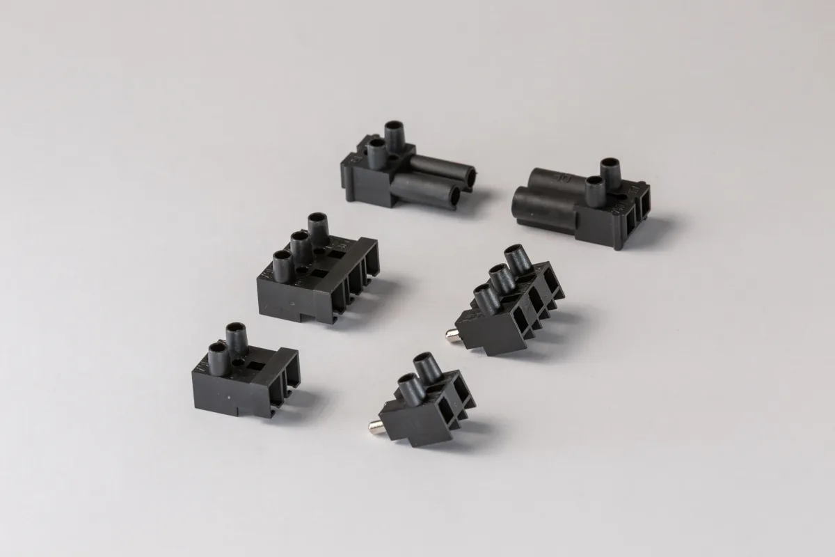
Six black two- and three-pole connectors made of engineering thermoplastic
Two- and three-pole connectorsPrecise plastic housings with fitted contacts, one version with IP20 protection.
Frame part with overmoulded metal clips, an example of a material composite
Aluminium-TPE hybridAluminium frame with adhesion-promoted TPE overmoulding and directly integrated sealing function.
Grey injection moulded inverter housing with ventilation slots and functional geometries
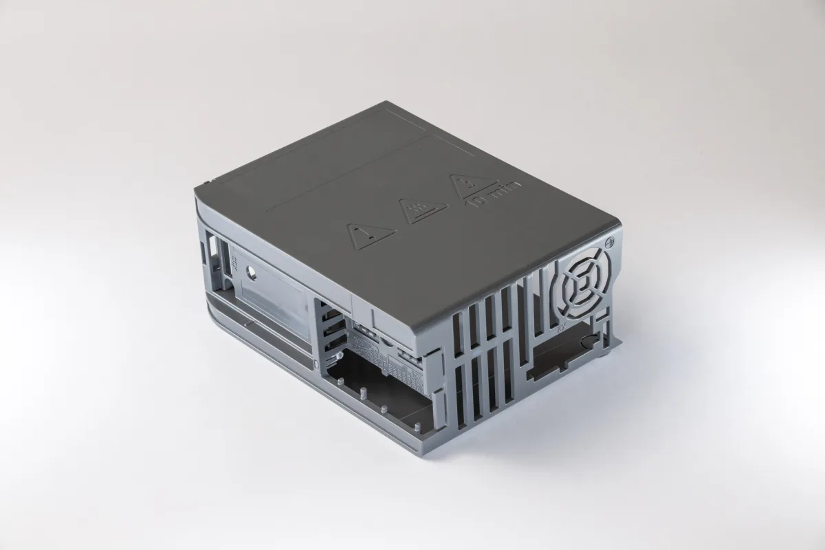
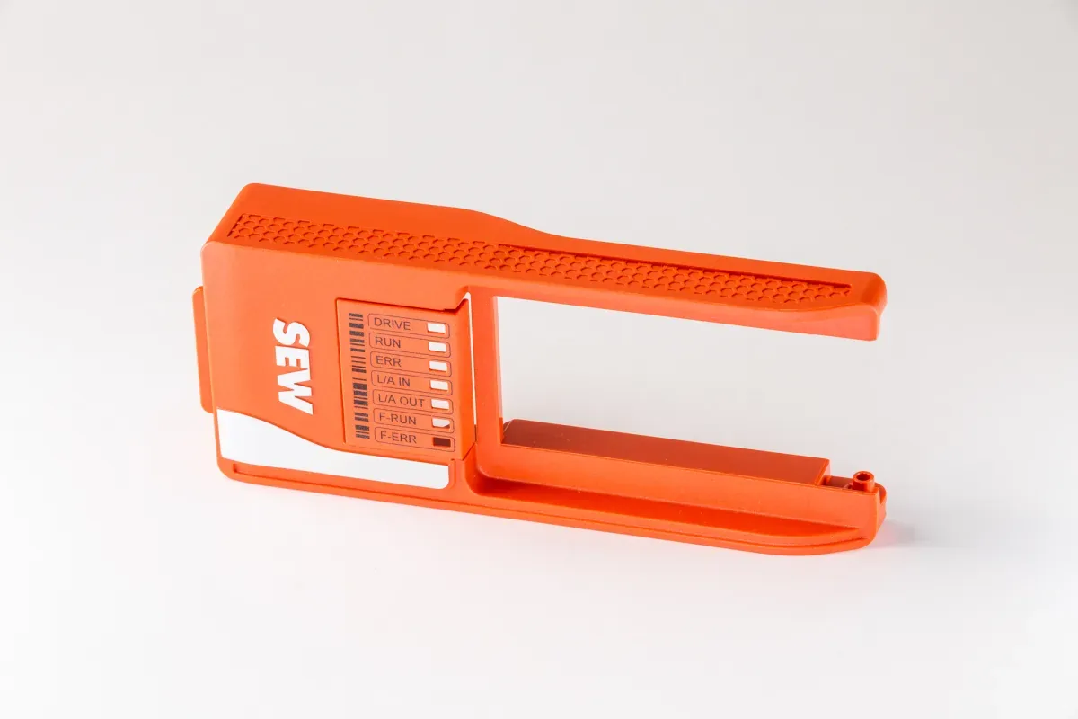
Housing for frequency invertersPlastic housing without draft angles, demoulded via four slides – for electronics and heat sink.

3D part in detail

360° from design data

A2362 · Seal integration

Multiple seal moulded in directly

A TPE multiple seal is moulded directly into the die-cast aluminium cover. It seals each individual light guide, is integrated in exact position and captively, and requires no additional assembly step.

Several light guides make status signals visible from different viewing directions. The smoke-grey, translucent cover hides the light guides when unlit and lets their signals through during operation. CNC-controlled printing, including the red design stripe, assigns the indicators to their respective functions.

Article
A2362 · Die-cast aluminium cover
Process
Moulding TPE in directly
Principle
Sealing in the mould
Function
Multiple sealing of the individual light guides
Black electronics housing with opened light grey lid, moulded-on seal all round and printed circuit diagram

From series production

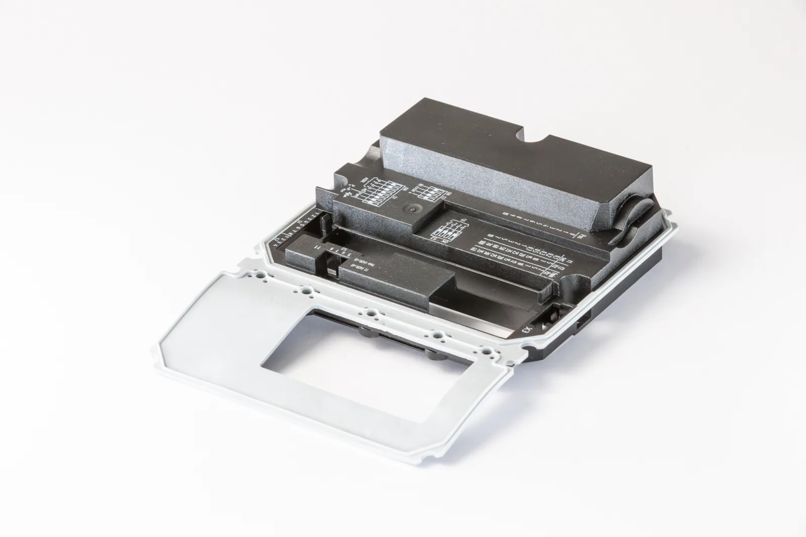
The electrical cover for an assembly with IP66 protection combines a dimensionally stable polycarbonate housing with a directly moulded-on TPE seal. Both components are produced in the 2K process in one mould. This eliminates separate assembly of the seal. The circuit diagram is then applied by CNC-controlled pad printing.

Frequently asked

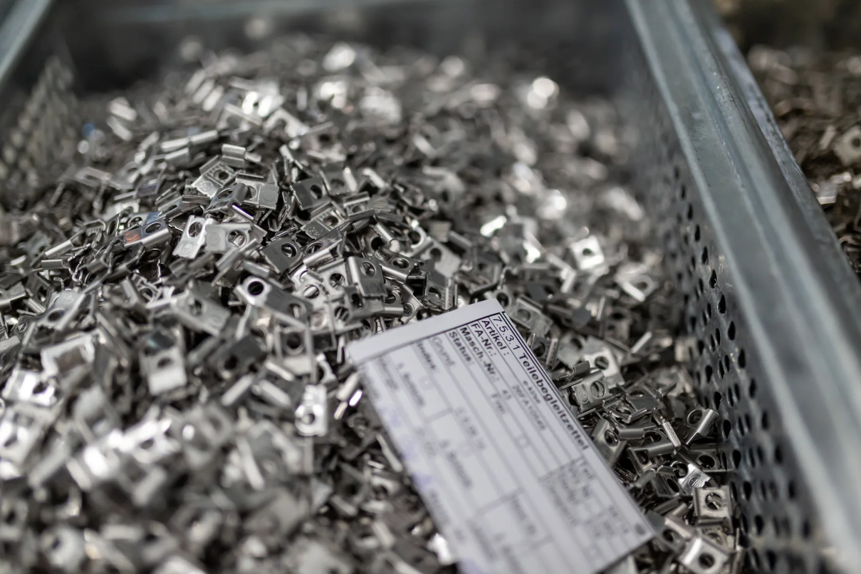
Finished stamped and bent parts from series production at Friedrich Joerg
05Capability

Stamping and bending technology

We produce contact parts, clamping bodies, plug and earthing contacts and clamping springs finished off the tool on Bihler stamping and bending machines and eccentric presses. We develop and build the precision tools required in our own toolmaking shop.

Many can stamp and bend. The difference lies in the depth of production and in mastering the entire process. Because we develop and build the precision tools in-house, we can match stamping, drawing, bending and thread forming precisely to each other. This allows even complex geometries to be produced reproducibly in series. Tool adjustments are made directly by us. This shortens coordination routes and speeds up implementation.

Material, surface and post-treatment depend on the later function. Depending on the requirements, we process pre-tinned strip or have the finished stamped and bent parts electroplated afterwards. Subsequent plating also covers the cut edges created beforehand. Lubricating and forming oils, which are needed for thread forming, for example, are removed by industrial parts cleaning. Where required, further process steps such as hardening or surface finishing follow. Many parts then go straight into our injection moulding and become part of a complete assembly.

4

Bihler stamping and bending machines, complemented by eccentric presses

THREADS IN THE PROCESS

Formed and hardened afterwards where required

FINISHED OFF THE TOOL

Ready-formed straight from the tool

What we can do

01

Series parts finished off the tool

On our Bihler stamping and bending machines and eccentric presses, we produce clamping bodies, contact zones, solder pins, springs, transistor clips, stainless steel brackets and other stamped and bent parts fully automatically in series. For dual-strip parts, two different metal strips can be fed in and processed into one part in an automated process.

02

Threads in the process

In clamping bodies, contact plates and other stamped and bent parts, we form metric internal threads directly in the running production process. With thin sheet metal, a collar is drawn first to create additional load-bearing threads. The thread is then formed without cutting. Where required, the parts are hardened afterwards. This creates resilient screw connections with a high torque reserve for typical installation conditions in the field.

03

Material by function

Our range of materials extends from highly conductive copper such as Cu-ETP through brass and tin bronze such as CuSn6 to hardenable and spring steels such as C45E, C67S or stainless chrome-nickel steel 1.4310. What matters is conductivity, spring force, strength, formability and corrosion resistance. For dual-strip parts, for example, a spring material and a highly conductive contact alloy can be functionally combined.

04

The link to plastic

Stamped contacts, solder pins and busbars can be transferred directly into insert moulding. Selectively tinned solder areas remain accessible, while other areas are overmoulded with plastic. The plastic geometry fixes and insulates the individual poles and takes the required clearance and creepage distances into account. This produces, for example, connectors with fewer individual parts and assembly steps.

Product examples

Stamped and bent metal clips
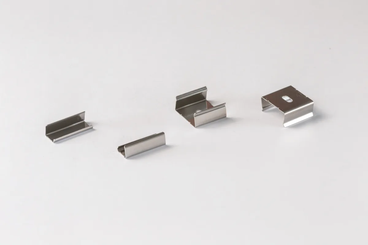
Stamped and bent parts made of spring steelPrecise parts made of stainless spring steel for building hardware and LED lighting.
Fine stamped and bent parts in several sizes
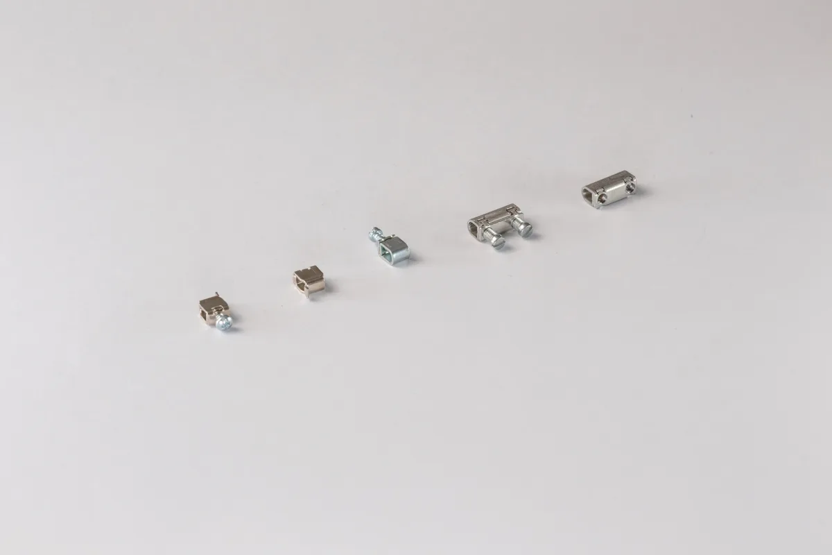
Screw clamping bodiesFormed metric thread and one or more clamping points for connection technology.
Stamped metal contact bodies
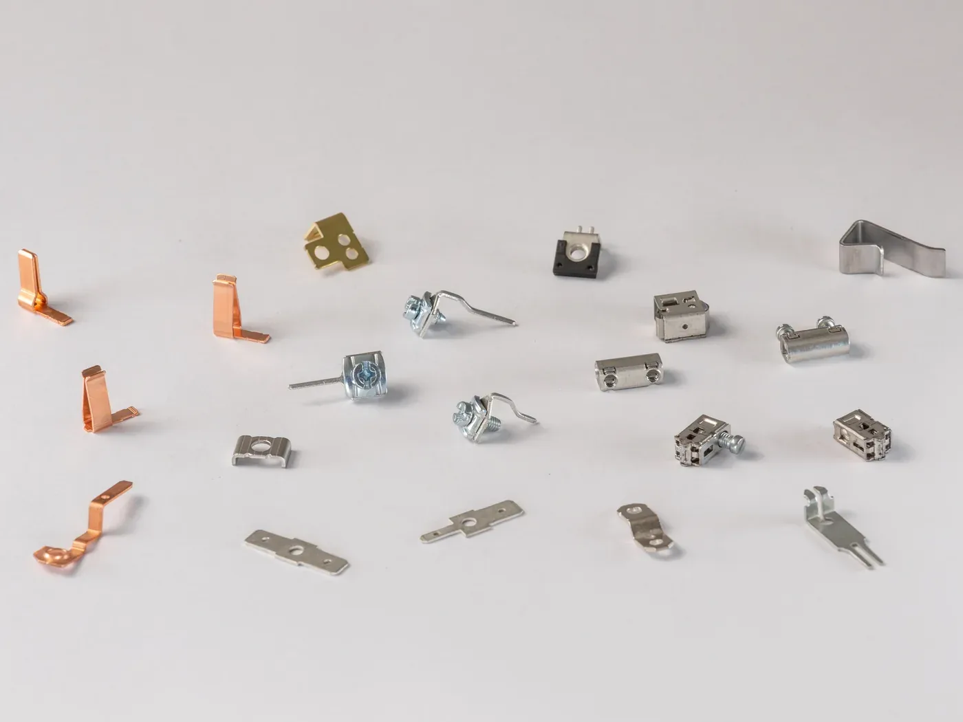
Contact parts made of various alloysFrom highly conductive copper to stainless spring steel – matched to the respective function.

3D part in detail

360° from design data

S8880 · Stamping and bending technology

From strip to three-dimensional clip

The RH clip is stamped out on an eccentric press and brought into its final three-dimensional geometry by several coordinated bending operations. This produces the part repeatably in series.

Article
S8880 · RH clip
Process
Stamping and bending on the eccentric press
Production
Series production in the stamping and bending die
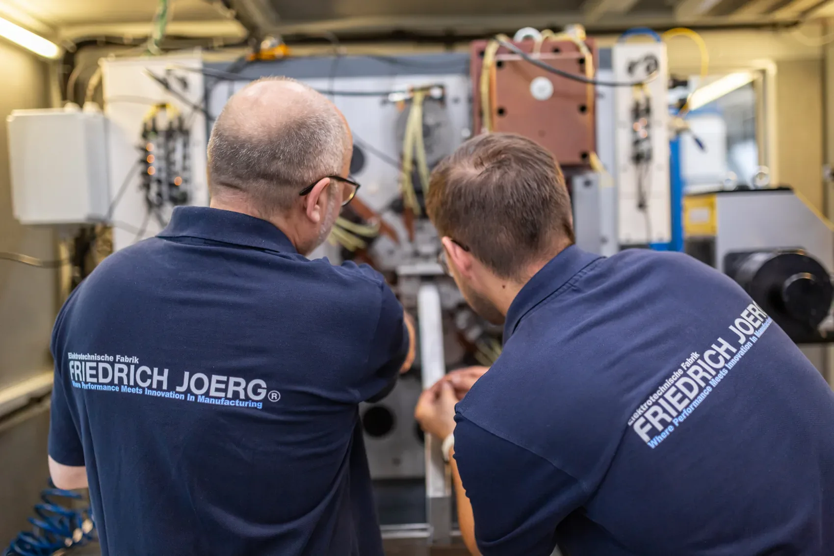
Two employees at the Bihler stamping and bending machine at Friedrich Joerg

From series production

Depending on the requirements, we produce clamping bodies for lighting components, connectors and motor connections from stainless strip steel or cold-rolled, hardenable steel such as C45E. Some versions come off the tool ready to install. Clamping bodies with formed threads are hardened afterwards where required. Depending on material and application, the surface is then tinned.

Frequently asked

Automated pad printing station: robot arm places the printing plate onto a part
06Capability

Finishing

The process steps that turn a part into a ready-to-install component or assembly: marking, joining and embossing. We carry out these finishing steps in-house, integrated directly into the production flow.

For us, finishing is not an outsourced final step, but part of the same process chain. We apply lettering, symbols and multi-colour print images by CNC-controlled pad printing, even onto uneven and complex geometries. Depending on the part and quantity, we integrate printing inline: robot removal, feeding to the printing system and placement ready for packing take place automatically. We join plastic housings by ultrasonic welding and transfer high-quality decorations by hot foil stamping. We machine functional surfaces where particularly tight tolerances or defined surfaces require it.

Processes that require specialised equipment and particular process knowledge are coordinated via long-standing partners. These include electroplated surface treatments, EMC coatings, chemical degreasing and heat treatments such as hardening and tempering. Technical specifications, supplier management and integration into the overall process remain with us. This means you continue to receive the part or assembly through one central interface.

What we can do

01

Pad printing (CNC)

The flexible silicone pad transfers single or multi-colour print images even onto uneven and complex surfaces. CNC-controlled, repeatable and, depending on quantity, fully automatically integrated into the production line.

02

Ultrasonic welding

On 20 kHz systems, we join thermoplastic housings with product-specific sonotrodes quickly and without adhesive. Material, joint geometry and process parameters are matched to achieve strong and, where required, media-tight bonds.

03

Hot foil stamping & precision machining

We transfer metallic, coloured or pre-printed decorations onto plastic parts using heat and pressure. We machine functional surfaces and dimensions where particularly tight tolerances or defined surfaces are required.

04

Special processes coordinated

Electroplated surface treatments, EMC coatings, chemical degreasing, hardening and tempering are carried out by specialised partners to our specifications. We coordinate the processes and integrate the results into our production and supply chain.

Product examples

Part with pad-printed scale and lettering
Finished visible plastic partSwivel cover with multi-colour pad printing and glossy hot foil stamping.
Printed metal rail with type plate and logo
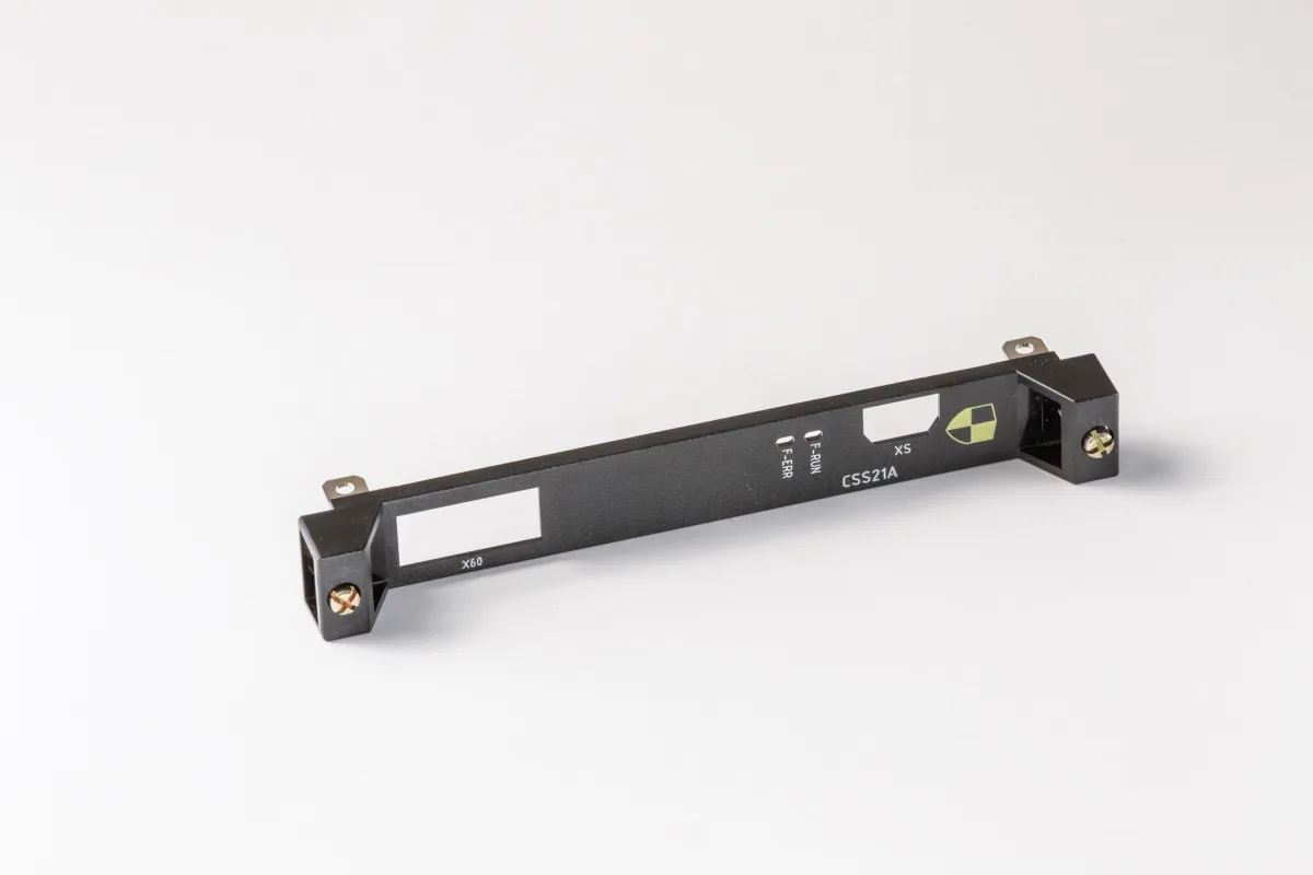
Printed front coverMulti-colour pad printing and ultrasonic riveting for captively integrated screws.
Terminal block made of black thermoplastic with tinned contact plates and clamping screws
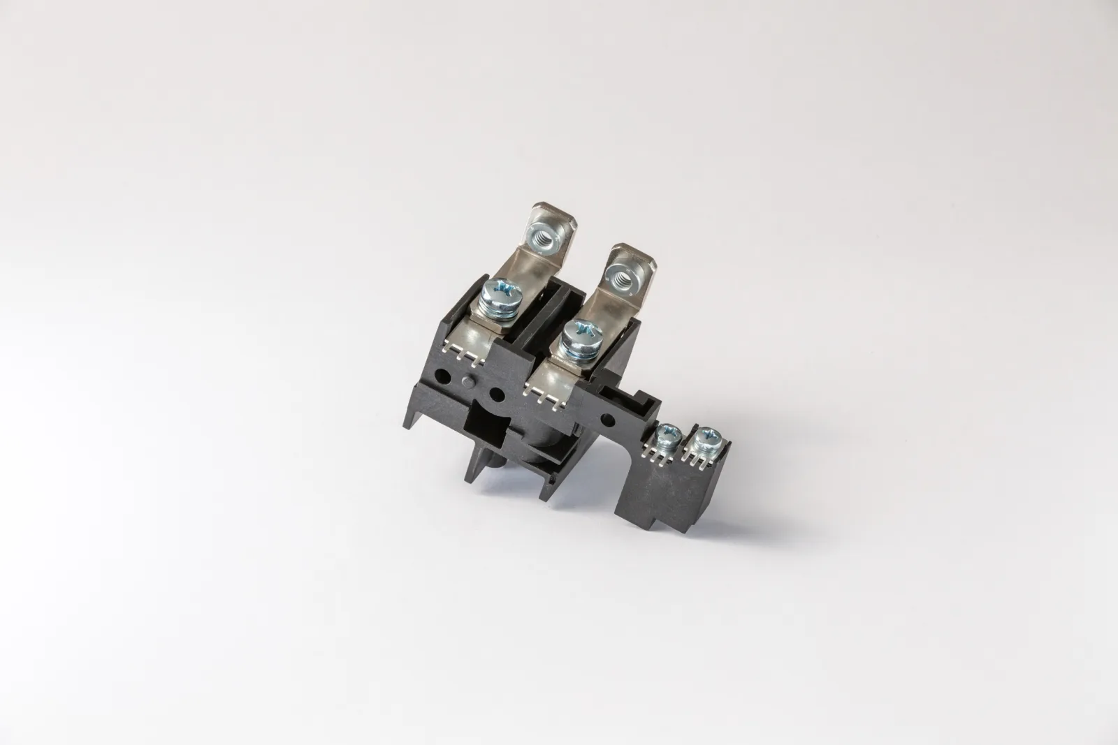
Power and signal terminal blockOvermoulded threaded bushes and electroplated stamped and bent parts combined ready for assembly.

3D part in detail

360° from design data

A2326 · Finishing

Decorative layer stamped on directly.

In hot foil stamping, the carrier foil is not incorporated into the part. A heated silicone stamp transfers the decorative layer on the carrier foil onto the plastic surface. On this swivelling cover, this creates a logo and a design stripe whose stamped image runs over a curved part contour.

Article
A2326 · ABD-MC/KL
Process
Hot foil stamping in the stroke process
Decoration
Logo and curved design stripe
Result
decorative layer stamped on directly
Automated pad printing cell: robot arm feeds an injection moulded part to the printing system

From series production

For suitable quantities, we integrate pad printing fully automatically into the production flow. A robot removes the injection moulded parts, feeds them to the CNC-controlled printing system and, after printing, places them ready for packing. This produces even multi-colour print images with positional accuracy and repeatability, without manual intermediate steps.

Frequently asked

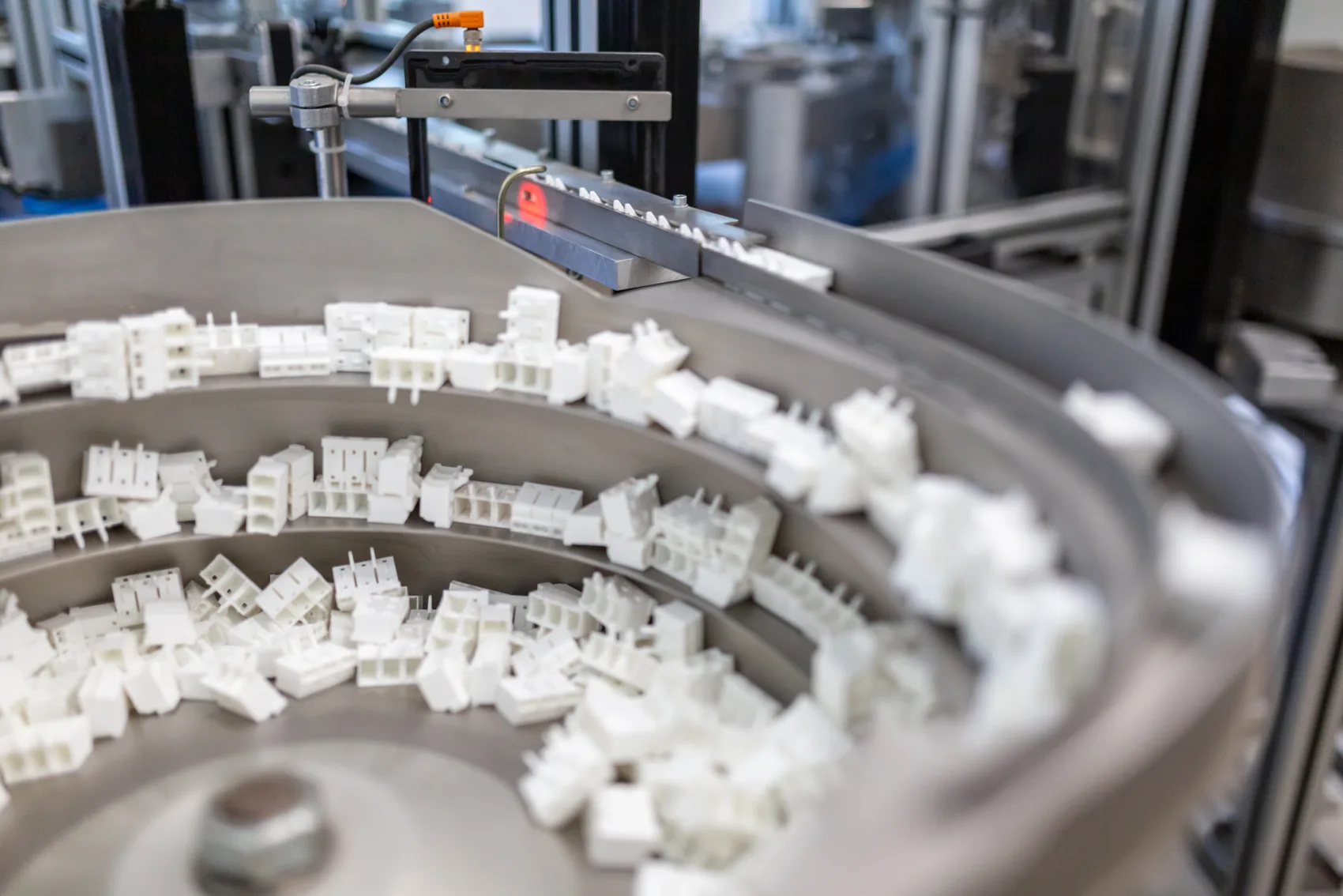
Vibratory bowl feeder with plastic parts on an assembly and feeding system at Friedrich Joerg
07Capability

Assembly & system supply

Individual parts become the ready-to-install assembly, inspected to the agreed inspection plan. We combine procurement, our own production, assembly and quality assurance, reducing your supplier interfaces. You give us a drawing, a parts list or an existing assembly status; we deliver the finished unit. One delivery, one invoice, one responsible contact.

As a system supplier, we combine our own production, bought-in parts, finishing, assembly, marking and packaging into an inspected, ready-to-install assembly. Contacts from stamping and bending technology, housings from injection moulding and externally sourced components come together with us in a coordinated process. Marking and packaging follow customer specifications, for example with Data Matrix or QR codes, and in returnable containers or thermoformed trays with exact position and orientation.

We also take on procurement to the agreed extent. We select standard parts for the application. Where required, we help design drawing parts, specify them and coordinate their procurement, for example for die-cast or machined parts. EDI, framework agreements, raw material planning with planning horizons of up to a year in some cases, and agreed stocks of semi-finished products and finished assemblies increase delivery capability and help to absorb short-term peaks in demand. This is how we reduce your supplier interfaces.
What we can do

01

Manual and automated assembly

From manual small series to automated large series. Marking with Data Matrix or QR codes and packaging to documented specifications, with exact position and orientation in returnable containers or thermoformed trays.

02

Standard and drawing parts

Selecting and sourcing standard parts; designing, specifying and buying in drawing parts where required. All components are matched to the function, assembly and quality requirements of the assembly.

03

Build-to-stock & EDI

Automatic order entry via EDI. Framework agreements, semi-finished products planned long term and agreed stocks of finished assemblies ensure high delivery capability and help to absorb short-term peaks in demand.

04

Ultrasonic welding

We join plastic housings by ultrasonic welding. For connectors, contacts and clamping bodies are pre-assembled, the housing parts welded and, where required, tested for leak tightness to the agreed test specification.

Product examples

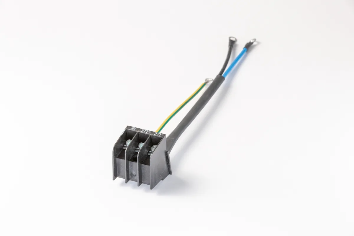
Wired three-pole terminal block with assembled cables
Wired terminal blockPad printing, overmoulded threaded bushes, fitted clamping screws and assembled cables.
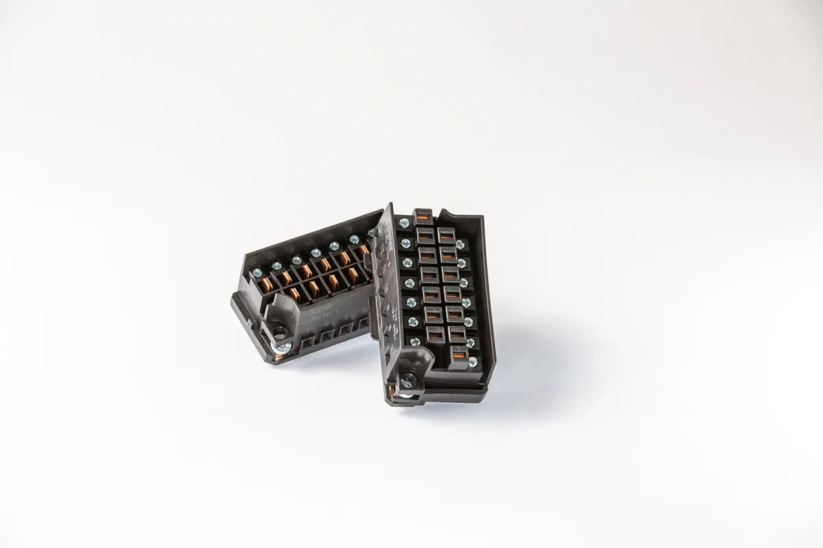
Two-part 14-pole motor connector, assembled ready to install
Motor connector 16 A / 690 V14-pole, automatically earthed and with our own copper contacts for fast motor changes.
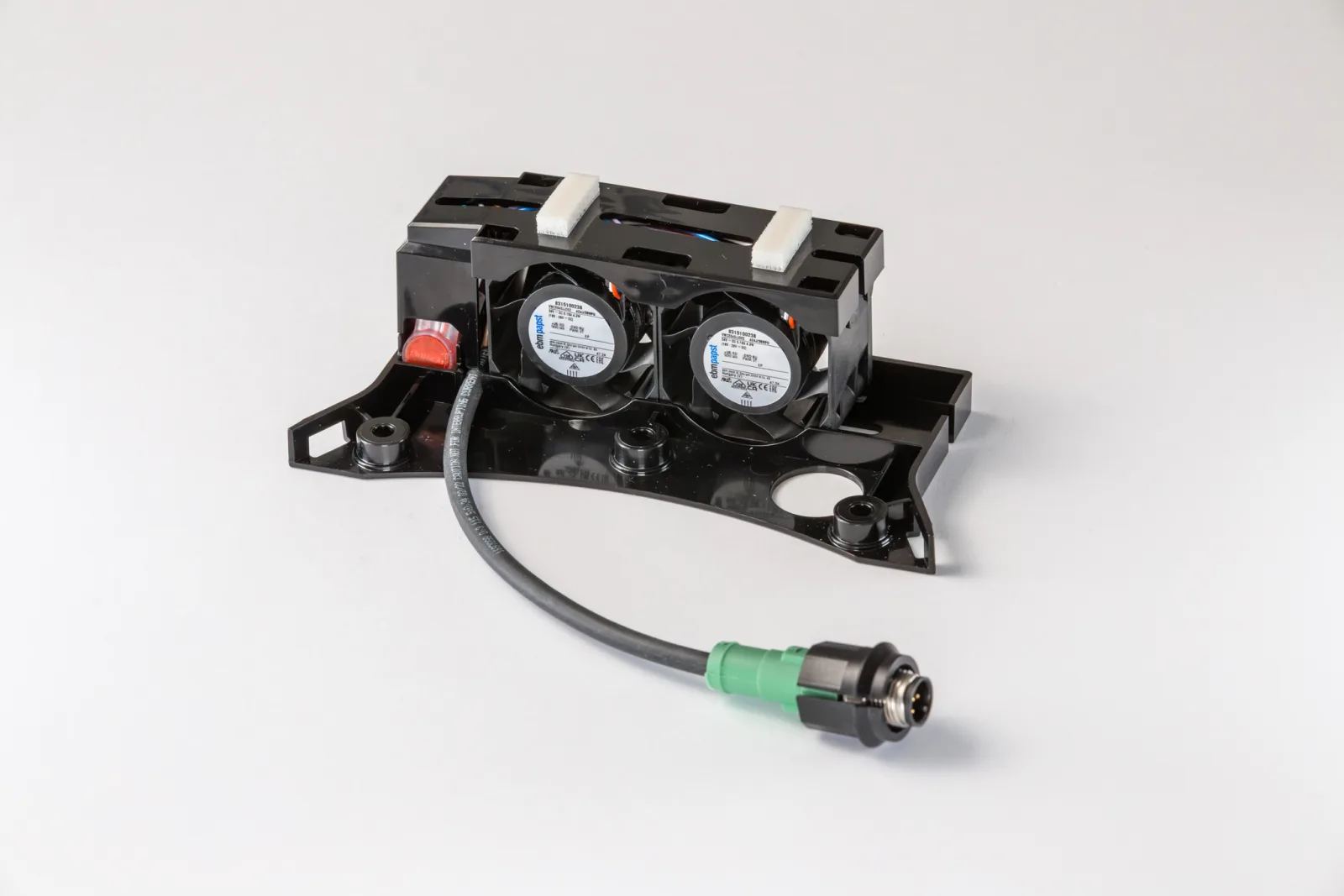
Fan assembly of two axial fans on a plastic carrier, with assembled cable and circular connector
100 % tested fan assemblyAssembled, wired using insulation displacement technology and electronically tested for performance, direction of rotation and signals.

3D part in detail

360° from design data

A2537 · Assembly & system supply

One assembly. One responsibility.

The five-pole terminal strip combines an injection moulded housing with five one-piece stamped contact plates with integrated solder pin and five combination terminal screws with formed clamping plate. When the screw is tightened, the inserted connecting wire is securely clamped between the clamping plate and the contact plate and electrically contacted. The solder pin provides the connection to the printed circuit board. All components are assembled fully automatically in-house into the ready-to-install assembly.

Article
A2537 · LK/SMD/K
Design
Plastic housing, contact plates and combination terminal screws
Function
Wire connection and contacting to the printed circuit board
Assembly
fully automated in-house
Delivery
ready to install and packed in trays

In-house work and specialised partners

  • Electroplated surfaces

    We produce electroplated surfaces with established, specialised partners. Depending on the requirements, we process pre-finished strip material or have finished stamped and bent parts coated. We take care of the technical coordination and integration into the production flow.

  • Cable assembly within the assembly scope

    We assemble cables and cable sets when they are part of an assembly we supply. Cable assembly alone as a separate contract service is not part of our range of services.

Assembly of an electromechanical assembly at Friedrich Joerg

From series production

For a connector for the power connection of industrial motors, we produce the housing and cover by injection moulding, and clamping bodies, copper contact parts and earthing tabs in stamping and bending technology. Standard parts such as screws are sourced as needed. All components are then assembled by us, and housing and cover are joined by ultrasonic welding to form the ready-to-install assembly.

Frequently asked

Optical measurement of a part at Friedrich Joerg
08Capability

Quality & metrology

For us, quality means mastering processes and detecting deviations before faulty parts leave production. We inspect throughout production, document the relevant results and work with a quality management system certified to DIN EN ISO 9001.

Quality is not created at the end, but in every production step. Incoming goods inspections, production releases, in-process inspections and initial sample inspection reports are integral parts of our quality management, certified to DIN EN ISO 9001. Inspection equipment monitoring, documented inspection results and systematic complaint handling ensure traceable releases and reliable series quality.

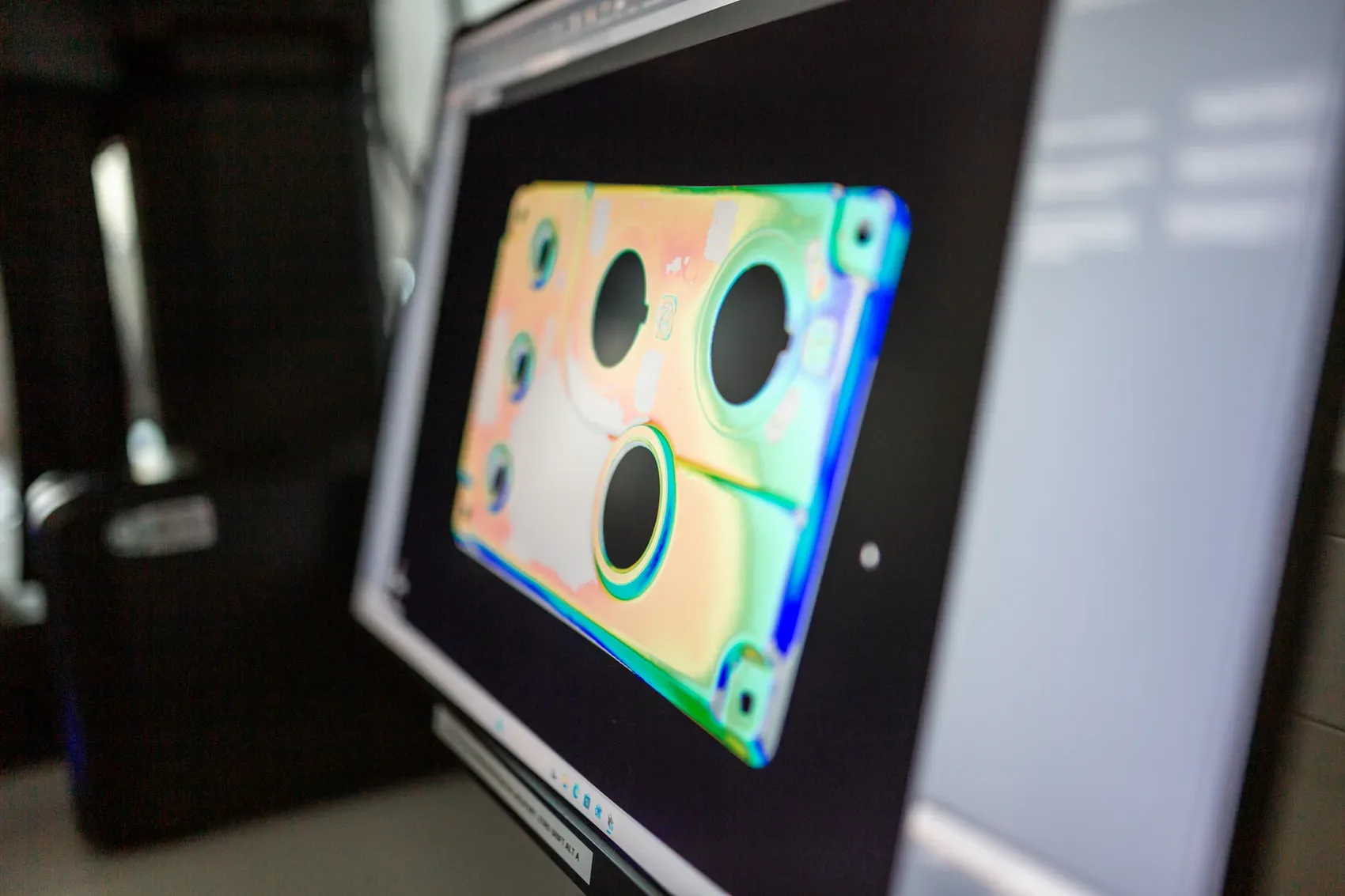
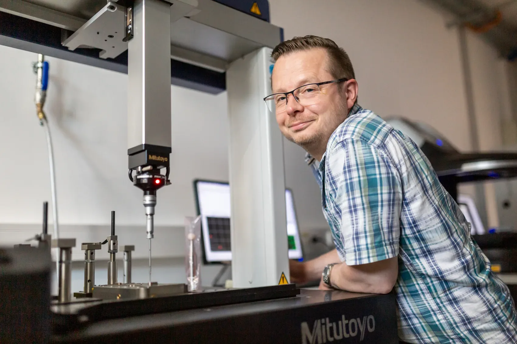
In our measuring room, we combine optical and tactile coordinate metrology. Complete 3D scans can be overlaid with the CAD target data. This makes deviations visible across the entire surface and allows parts or production stages to be compared directly. Measuring microscopes and hardness, torque and force measurements add function-relevant data to the dimensional inspection. Findings feed straight back into the tool and the production process.

1.47 ppm

Internally determined customer ppm (December 2025)

DIN EN ISO 9001

Certified quality management

Optical & tactile

Coordinate metrology in our own measuring room

What we can do

01

Inspection in the process

Incoming goods inspection, production releases, in-process checks and initial sample inspection with documented results and monitored inspection equipment.

02

Optical & tactile measurement

Complete 3D scans with CAD target/actual comparison and tactile measurements of defined geometries, in automated measuring sequences where required.

03

Microscopy & inspection equipment

Measuring microscopes with incident and transmitted light, hardness testing, thread gauges, callipers and micrometers complement the coordinate metrology.

04

Force & torque

Electronic torque measurements record not only peak values but also the curve. Tensile and compressive force measurements test, for example, pull-out and release forces on contacts and plug connections.

Optical coordinate measuring machine at Friedrich Joerg

Traceable

For every article delivered, batches, process steps and material movements are documented. This means its path can be traced back without gaps to the incoming goods inspection of the materials and bought-in parts used.

Frequently asked

From a single process to the complete assembly.

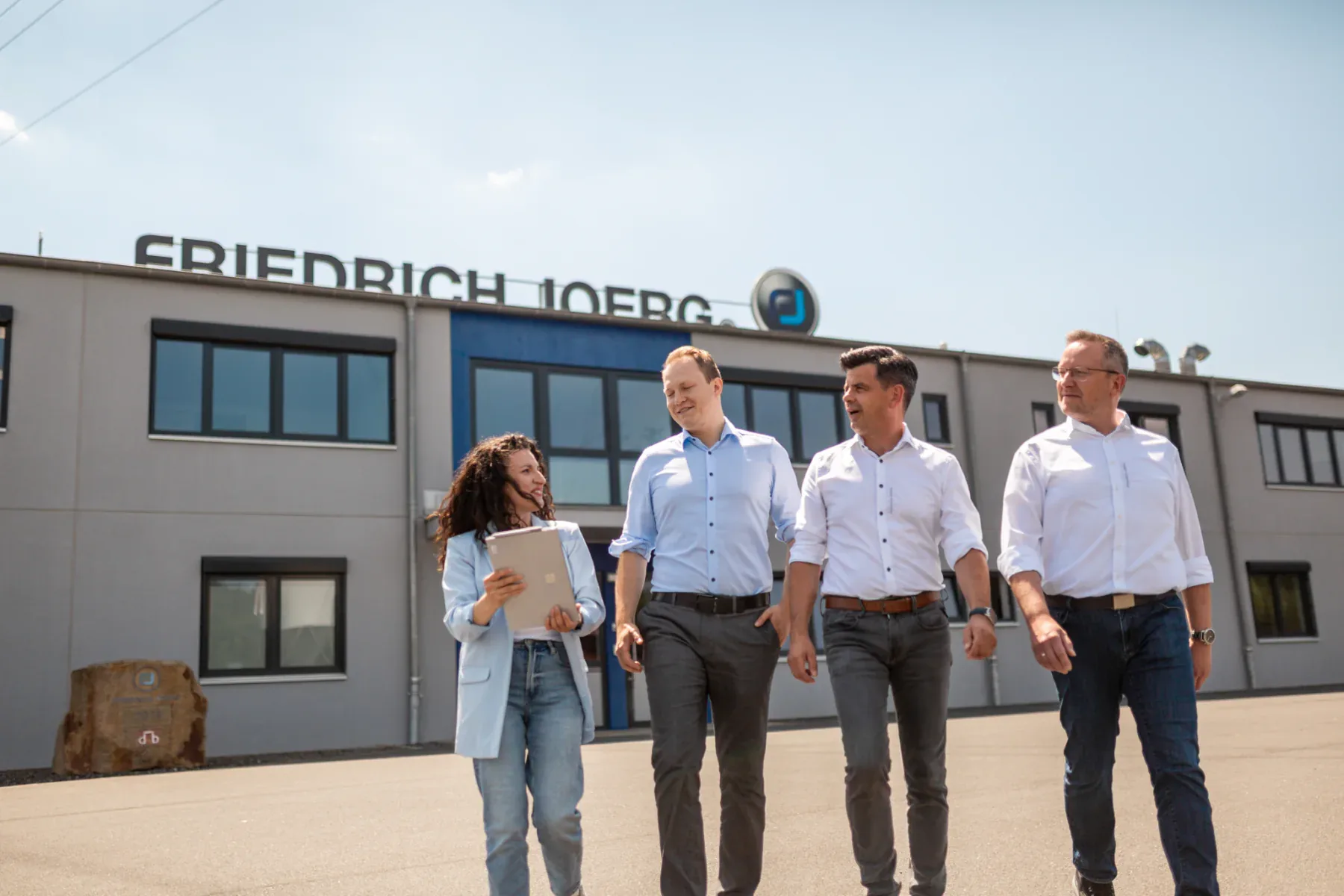
Friedrich Joerg team in front of the company building in Marktrodach

Send us 3D data, a drawing, a specification or a sketch. As a rule, you will receive an initial technical assessment of feasibility and next steps within two working days.

    Privacy · Your choice

    We would like to measure which adverts work and load external content.

    For this we use cookies and similar technologies: LinkedIn and Meta (Facebook, Instagram) measure which adverts lead to visits and enquiries; wlw (Visable GmbH) identifies which companies visits come from. The map (OpenStreetMap Foundation), Instagram posts and route planning with Google Maps only load after you consent. With LinkedIn, Meta and Google, data is also transferred to the USA. With “Convenience” we remember your choice for 12 months, otherwise only for this visit. You can change your choice at any time via the privacy settings in the footer.

    Privacy policyLegal notice